

Hey there! As a supplier of the Thin Butt Series Laser Weld Tracking Sensor, I'm stoked to share with you how to install this awesome piece of tech. Whether you're a welding pro or just getting into the game, this guide'll walk you through the process step by step.
What's the Thin Butt Series Laser Weld Tracking Sensor?
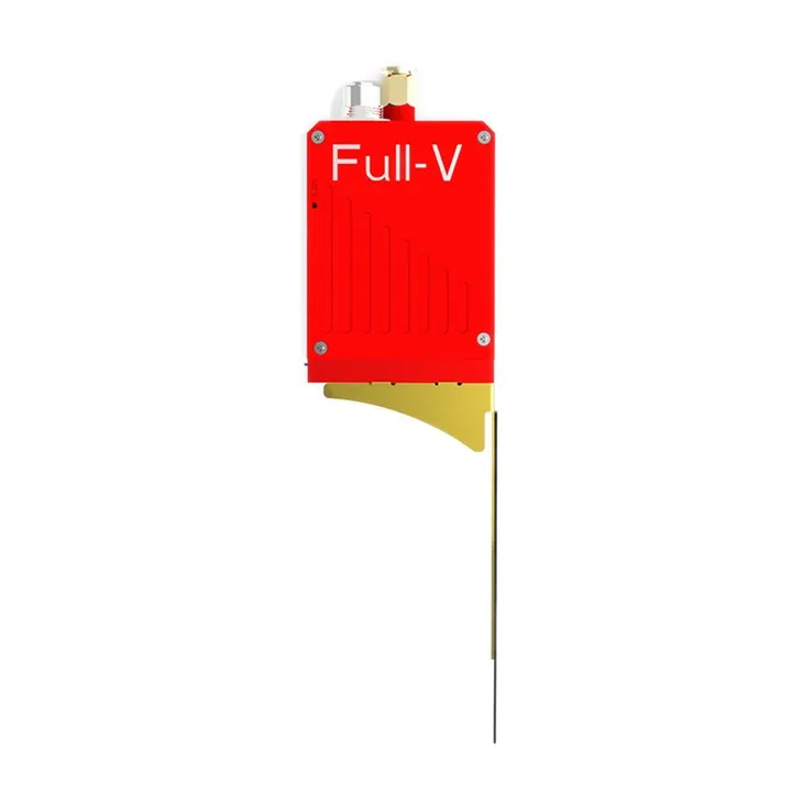
Before we jump into the installation, let's quickly chat about what this sensor is all about. The Thin Butt Series Laser Weld Tracking Sensor is a top - notch tool designed to improve the accuracy and efficiency of your welding operations. It uses laser technology to detect the weld joint in real - time and make adjustments on the fly, ensuring a perfect weld every time.
We've got two cool models in the series: the Butt Series Laser Weld Tracking Sensor FV - 150 - ZO - TD and the Butt Series Laser Weld Tracking Sensor FV - 210 - ZO - TD. Each has its own set of features and capabilities, so you can choose the one that best suits your needs.
Pre - installation Checks
First things first, you gotta do some pre - installation checks. This'll save you a lot of headaches down the road.
- Inspect the Sensor: Take a good look at the sensor when it arrives. Check for any visible damage like cracks, dents, or loose parts. If you find anything wrong, don't try to install it. Contact us right away, and we'll sort it out.
- Gather the Tools: You'll need a few basic tools for the installation. These usually include a screwdriver, a wrench, and some cable ties. Make sure you have everything ready before you start.
- Check the Mounting Location: Decide where you're gonna mount the sensor. It should be close to the weld joint but not so close that it gets damaged by the heat or sparks. The surface where you'll mount it needs to be flat, clean, and free of debris.
Installation Steps
Step 1: Mount the Sensor
The first step is to mount the sensor. Here's how you do it:
- Position the Bracket: Most of our sensors come with a mounting bracket. Place the bracket on the chosen mounting surface and mark the holes where you'll need to drill.
- Drill the Holes: Use a drill to make holes in the marked spots. Make sure the holes are the right size for the screws that came with the bracket.
- Attach the Bracket: Insert the screws through the holes in the bracket and tighten them with a screwdriver or a wrench. Make sure the bracket is firmly attached to the surface.
- Mount the Sensor on the Bracket: Once the bracket is in place, you can mount the sensor on it. Line up the holes on the sensor with the holes on the bracket and use the provided screws to secure it.
Step 2: Connect the Cables
After mounting the sensor, it's time to connect the cables.
- Power Cable: Find the power cable that came with the sensor. Connect one end to the power input port on the sensor and the other end to a suitable power source. Make sure the power source has the correct voltage and current ratings.
- Communication Cable: Connect the communication cable to the communication port on the sensor. The other end of this cable will usually go to your welding control system. This cable allows the sensor to send and receive data.
- Cable Management: Use cable ties to keep the cables organized and prevent them from getting tangled. Make sure the cables are not too tight or too loose and that they're out of the way of moving parts.
Step 3: Calibrate the Sensor
Once the sensor is mounted and the cables are connected, you need to calibrate it.

- Initial Setup: Power on the sensor and the welding control system. Follow the instructions in the user manual to perform the initial setup. This usually involves entering some basic information like the type of weld joint and the material you're welding.
- Positioning Calibration: The sensor needs to be correctly positioned relative to the weld joint. Use the calibration tools provided to adjust the position of the sensor until it can accurately detect the weld joint. This may take a few tries, so be patient.
- Sensitivity Calibration: Adjust the sensitivity of the sensor so that it can detect the weld joint clearly without being affected by background noise or interference. You can do this by following the calibration procedure in the user manual.
Post - installation Checks
After you've completed the installation and calibration, it's important to do some post - installation checks.
- Visual Inspection: Take another look at the sensor and the cables. Make sure everything is properly connected and that there are no loose parts.
- Function Test: Run a test weld to see if the sensor is working correctly. The sensor should be able to detect the weld joint and make the necessary adjustments to the welding process. If you notice any issues, refer to the troubleshooting section in the user manual or contact our support team.
- Data Monitoring: Check the data being sent by the sensor to the welding control system. Make sure the data is accurate and that there are no errors or warnings.
Tips and Tricks
- Keep it Clean: Regularly clean the sensor to prevent dust and debris from building up on the lens. This can affect the sensor's performance.
- Update the Firmware: Periodically check for firmware updates for the sensor. These updates can improve the sensor's performance and add new features.
- Training: If you're new to using a laser weld tracking sensor, consider getting some training. This'll help you make the most of the sensor's capabilities.
Conclusion
Installing the Thin Butt Series Laser Weld Tracking Sensor isn't too complicated if you follow the steps outlined in this guide. By doing a proper pre - installation check, carefully mounting the sensor, connecting the cables correctly, and calibrating it accurately, you'll be able to get the most out of this amazing tool.
If you have any questions during the installation process or if you're interested in purchasing one of our sensors, don't hesitate to reach out. We're here to help you with all your welding needs and ensure that you have a smooth and successful experience with our products.
References
- Thin Butt Series Laser Weld Tracking Sensor User Manual